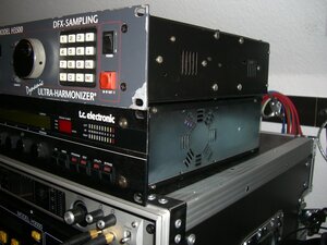
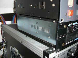
t.c. electronic M5000 PSU upgrade
 While the M5000 is a truly marvellous professional effects unit from t.c. electronic, the PSU heat dissipation and ventilation design leaves a lot to be desired. The PSU gets hot, there is no fan and passive ventilation is only possible through the unit's sides. PSU failure is only a matter of time. You've got to ask “when”, not “if”.
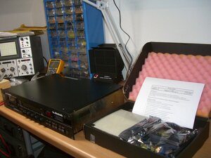
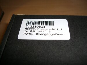
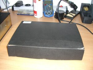
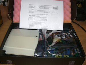
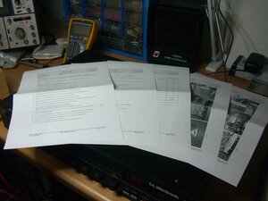
Luckily though t.c. still distributes a PSU upgrade kit that upgrade the M5000 PSU to M6000 spec. I found out about this by searching for a PSU solution and stumbled through forum posts until I ended up at Gary Faller Engineering Inc. and found the crucial hint. In Germany I ordered the kit from PMS electronics GmbH. Step by step instructions are included but you should be able to handle a soldering iron; And you need to be really careful not to damage or short circuit the battery.
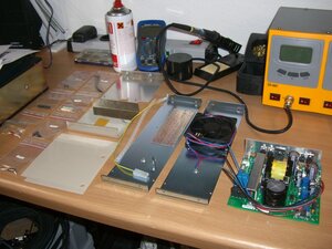
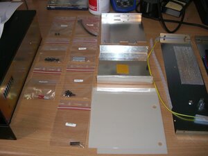
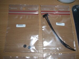
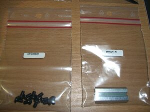
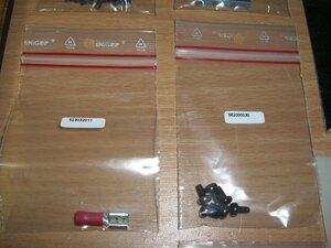
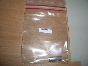
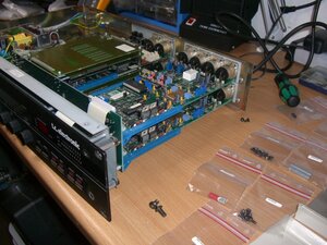
The kit
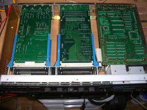
Dismount the top and bottom lids
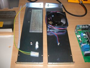
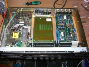
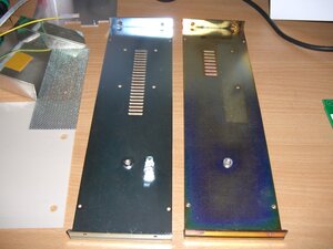
Replace right side panel
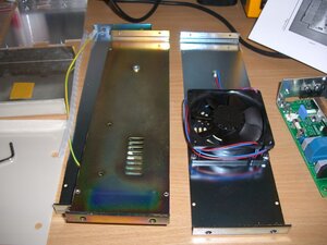
Replace the right side panel with the new side panel fitted with the fan.
Use the cable tie for fastening the fan wires. I postponed the fastening step until the end, where all wires need to be fastened.
Disconnect 6 power wires at J7 on BUS PCB
Unplug connectors CN1 and CN3 at PSU PCB
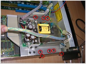
Remove mounting panel and PSU PCB
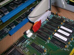
Disconnect FDD cables at CPU PCB
Remove FDD
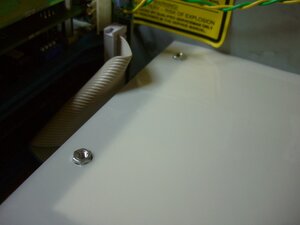
Replace spacers
Replace left side panel with the new left side panel
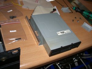
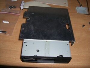
Mount FDD on the new mounting panel
Take the FDD and remove the two metal holders by unscrewing 4 screws. Mount the FDD on the new mounting panel by use of two screws.
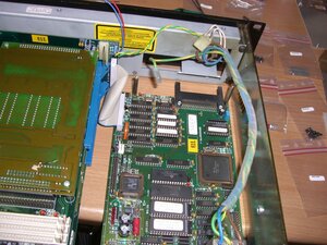
Put in FDD again
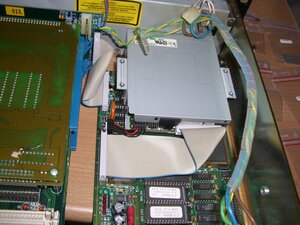
Push down the CPU PCB a little and carefully slide in the FDD again. For mainframes with CPU PCB ver. M5000-5 or M5000-6:
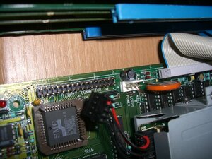
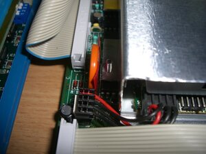
- Make sure the mounting panel doesn't short circuit the battery.
- Make sure the coil L1 fits into the hole in the new mounting panel.
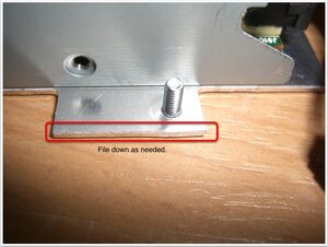
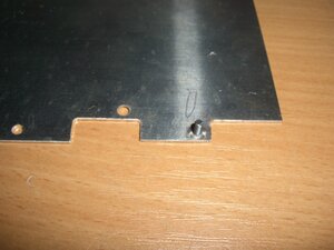
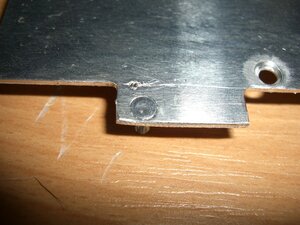
In order to not short circuit the battery I had to file down part of the mounting panel. In addition to that I placed some adhesive tape against the battery just to be sure. This can later be removed again after the panel has been fastened.
Mount the new metal shield on the floppy drive by help of the tape attached to the metal shield.
Attach the CPU PCB to the new mounting panel by use of two screws. Attach the new mounting panel to the side panel by use of two screws. Then connect the two FDD cables to the CPU PCB again. Mount the two new spacers on the new mounting panel.
Customize wires from AC inlet
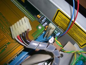
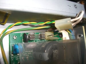
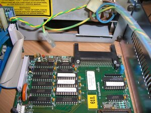
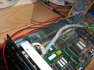
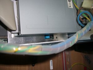
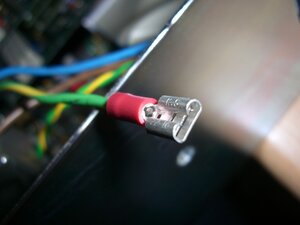
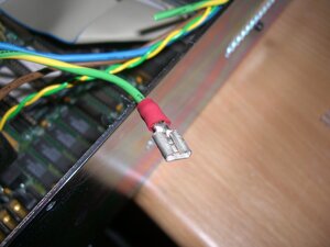
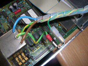
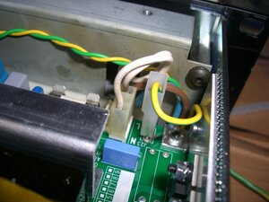
Remove the spiroband wrapped around the wires from AC inlet. Reduce the length of the yellow/green wire from the AC inlet. New length = 3.5inch / 8.8cm. Mount/solder the crimp terminal and housing on the wire.
Reconnect AC inlet wires
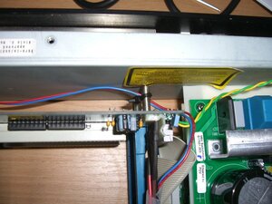
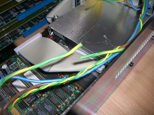
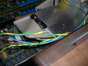
Connect the newly crimpedd terminal and one end of the new long yellow/green wire to the side panel. Wrap the spiroband around the 5 wires (2 wires from AC inlet, 2 ground lift wires, 1 long yellow/green wire). Place the 5 wires in the gap between the side panel and the FDD.
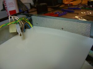
Place insulation shield
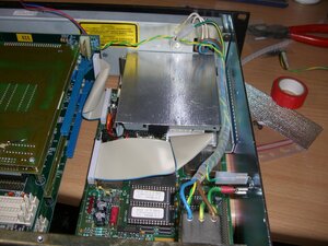
Place the new insulation shield on top of the FDD. Make sure the two spacers fit into the holes. Place the metal net at the side panel.
Connect power supply unit
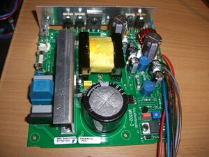
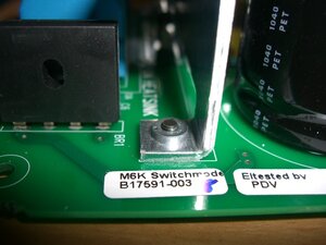
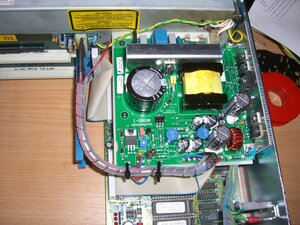
Place the new PSU PCB on top of the new insulation sheet. Attach the PSU heatsink to the side panel by use of two screws. Attach the PSU PCB to the two spacers by use of two screws.
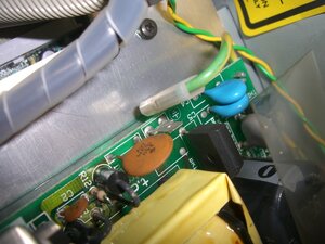
Connect the long yellow/green wire to J23 on the PSU PCB. Connect the two power switch wires to J2 on the PSU PCB. Solder in the two wires from the fan, blue wire to J3 pin1 and red wire to J3 pin2.
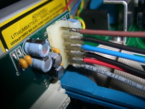
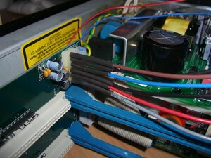
Solder the 6 wires from the PSU into J7 on the BUS PCB. Take care to avoid short circuits and take extreme care to place them in correct order.
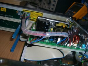
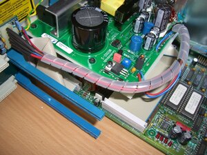
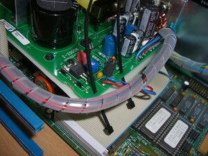
Wrap the new spiroband around the six PSU wires and the two fan wires.
Use the cable ties for fastening the wires to the PSU PCB.
